Showing all 5 results
CDI Flow Cells, CO2 Electrolysis Accessories, ...
795.00 € Add to Quotation This product has multiple variants. The options may be chosen on the product page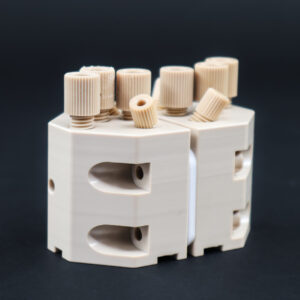
CDI Flow Cells, CO2 Electrolysis Cells, ...
From: 1,955.00 € Add to Quotation
CDI Flow Cells, CO2 Electrolysis Cells, ...
From: 1,395.00 € Add to Quotation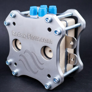
CDI Flow Cells, CO2 Electrolysis Cells, ...
From: 2,826.00 € Add to Quotation
CDI Flow Cells, CO2 Electrolysis Cells, ...
From: 3,320.00 € Add to QuotationElectrochemical CO2 reduction (CO2RR) holds immense potential for mitigating climate change by converting CO2 into valuable chemicals and fuels. Over the last decade, significant advancements in research and development have accelerated this field with the discovery of new catalysts and new process concepts. Advances in electrolyzer designs and operating conditions have improved reaction rates, product yields and overall energy efficiency. These developments have brought CO2RR closer to industrial-scale implementation, offering a promising pathway to a carbon-neutral future.
Here the Redox-Flow electrochemical flow cells are unique because they are designed as building blocks where different electrodes, membranes, materials, process concept and active areas can be tested built from the same platform.
Below is are some considerations on materials selections followed by examples Redox-Flow electrochemical CO2 electrolysers.
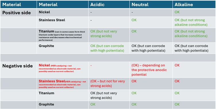
Material choices for the components in the CO2 reduction cells are extremely important. Several considerations have to be taken into account and is in the end a trade-off between different parameters. Not considering catalysts, the typical materials (current collectors and electrodes) used are stainless steel (316 L), titanium, nickel and graphite based composites. The overall considerations are the following:
For the CO2 reducing side of the cell it is preferable to use materials that do not catalyse H2 evolution (HER) as this will be a competing parasitic reaction. Here typically stainless steel and nickel are relatively good catalysts for HER, while titanium and carbon has high overpotential for HER and are the preferred materials for both current collectors and porous electrodes.
Depending on the exact CO2 reduction reaction process, it can be in liquid phase under different pH conditions ranging from acidic to alkaline. Here it is only titanium and graphite that are corrosion resistant in the full pH range, while stainless steel and nickel are only stable from neutral/mild alkaline to strongly alkaline solutions. Typically, the corrosion stability of materials can be seen from their respective Pourbaix diagrams, however, they are typically calculated based on thermodynamic properties and do not take the reactions kinetics/rates into account. However, more importantly during electrolysis processes the local pH close to the electrode surface will change due to concentration polarisation. Or in more simple terms, the CO2 reducing side consumes protons whereby the local environment becomes more alkaline. On the oxygen evolution side (OER) hydroxide ions are consumed or protons are produced, whereby the local pH close to the electrode or bipolar plate surface decreases. As an example, a typical Pourbaix diagram for nickel suggest that it is stable in pH down to 7. However, if it is used as electrode for oxygen evolution it will most likely corrode do the pH in the electrode surface is decreased into the acidic range where it dissolves into the solution. Setting exact pH ranges is impossible as the corrosion rates depends on many parameters such as temperature, operation conditions (high/low electrical currents), flow rates, formulation of electrolyte etc.
As can also be seen from Pourbaix diagrams, all materials becomes stable against corrosion if a sufficiently low potential is applied to them. This can be exploited for materials for the negative side, where the negative potential can lead to ‘anodic protection’. As an example, nickel is not stable in acidic solutions, however, if a potential of about -0.5 VSHE is applied, it becomes anodically protected. However, this protection will only work if the potential is applied constantly (which can be difficult), so it is in general not recommended to use anodic protection to reduce corrosion.
On the positive side the materials can also be corroded by oxidative stress due to the applied positive potential that will oxidise the materials. Here, typically all metals (stainless steel, nickel and titanium) forms protective metal oxide layers, while graphite is prone to corrosion. However, the rate of graphite corrosion depends on the applied half cell potential (e.g. vs SHE) and can in some cases be used as bipolar plate material and electrode (but only for relatively low potentials)
The above considerations have been compiled into the table below where the green is recommend materials for the specific condition, red are not recommended, while black are possible to use it. It is noted that nickel and stainless steel are not recommended as electrode material for the negative side as they catalyse parasitic HER. Under certain conditions they can be used as current collectors (as the surface area here in many cases is much smaller than that of the electrodes). As an example, a nickel current collector can in some cases be combined with a carbon based electrode.
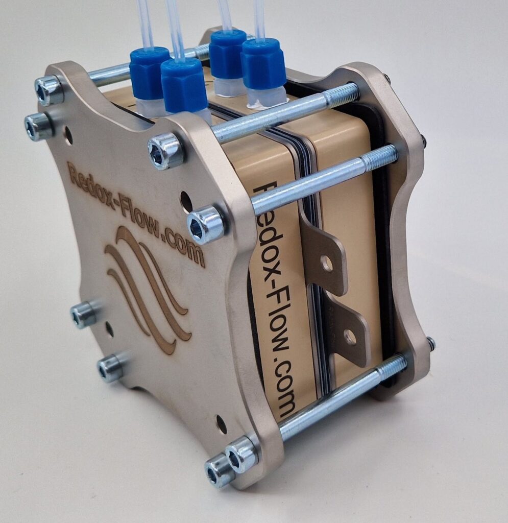
Below are three examples of CO2 reduction cells that can be built from Redox-Flow components. The examples are inspired by some the cell concepts from the following articles (https://doi.org/10.1016/j.cherd.2024.07.014, https://doi.org/10.1016/j.jcou.2019.09.007, https://doi.org/10.1016/j.isci.2022.104011 ). They have been divided into 2, 3 and 4 compartment cells and all come with Titanium current collectors with flow field. Titanium is an all-round material that is corrosion resistant in almost full pH range. However, it can also be replaced with a carbon based interface (from the S-cell) on e.g. the negative side only. Also current collectors with flat surface can be used (e.g. for thicker electrodes).
This example is based on our X-cell with additional ports. In the negative side CO2 is fed to a (thin) metal or carbon based electrode coated with CO2R catalyst. Here the gas phase products (e.g. CH4) leaves the cell from the outlet. The positive side is constructed similarly with a (thin) electrode coated with oxygen evolution reaction (OER) catalyst, where O2 is produced from H2O. The two chambers are separated by an ion exchange membrane where ions are transported from one to the other side to ensure charge balance. For both sides a titanium current collector with flow field is used.
The example is shown with gas phase reactants, however, it can equally well be used for liquid phase reactants. E.g. carbonated (CO32-) dissolved in (mild) alkaline solutions.
If the cell with additional ports is used, it is possible to form a Luggin capillary (shown by the red dotted line going through the cell) to the membrane surface inside the cell. It can be used for measuring the potential between the membrane and the negative side current collector, which is typically associated with overpotential for CO2 reduction. Here Redox-Flow also offers an electrode holder that will make the measurement easy.
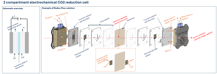
Some of the shortcomings of using the two compartment cell is that liquid phase products (e.g. formic acid HCOOH) continuously will concentrate in the electrode (if gas phase CO2 is used). Depending on the membrane is can also cross-over to the positive side where it potentially will be oxidized back to CO2.
To mitigate this (to the best of Redox-Flow’s knowledge) the three compartment CO2 reduction cell was developed. Here gas phase CO2 is reduced on Gas Diffusion Electrode (GDE) coated with a catalyst coated gas/liquid interphase. CO2 is reduced into a water soluble molecule that diffuses into the liquid phase of a central chamber of the cell. On the electrochemically positive side of the cell oxygen is produced through a catalyst coated GDE.
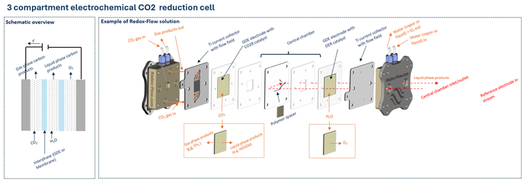
The Redox-Flow concept for this cell is based on a X-cell with additional ports to form a three compartment cell. The hydraulic circuit is shown by the red dotted line and enters/exits at the end of the positive side. The outer compartments (half-cell) are for electrochemical CO2 reduction and oxygen evolution reactions, while the central chamber supplies water for the reactions and also becomes the solvent for the reduced CO2 molecule. The GDEs are kept tight from leaking to the surrounding of the cell by a ‘GDE gaskets’, while the internal leak integrity is provided by sealing the GDE together with the ‘GDE gasket’ with a thin tape.
As for the other examples, there is full freedom to choose other current collector materials (nickel, stainless steel and carbon based) with and without flow field. However, the most important is to underline that it can the gas diffusion electrodes can also be replaced with ‘normal’ electrodes and membranes. The only difference being slightly different gaskets.
For three compartment cells a reference electrode can be connected to the central chamber liquid stream by the Redox-Flow flow though electrode holder. This can be used for measuring the CO2 reduction overpotential.
This example is a four compartment cell based on the X-cell with additional ports. The two outermost compartments (half-cells) are gas-phase for CO2 reduction and OER, respectively. These two compartments are separated by GDEs with catalyst coating for CO2 reduction and OER, respectively. Gas phase products (e.g. CH4 and O2) exits through the two outmost chambers. The hydraulic circuit of the two inner chambers are shown by the red dotted lines. The negative side central chamber exits on the negative and vice versa. The two central chambers are separated by an ion exchange membrane.
By Redox-Flow it is anticipated that the four compartment cell is a further development of the three compartment cell. Here the liquid products enters into the single central chamber and can then be oxidized back to CO2 when it gets in contact with the positive side GDE. In the four compartment cell this is mitigated by including a membrane that effectively ensures that the carbon products do not get in contact the the positive side GDE.
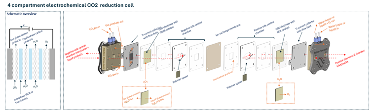
As for the other cells, the GDEs are kept leak free by a special gasket that is sealed with tape. Also any of the GDEs can be replaced with standard electrodes (e.g. carbon paper) and ion exchange membrane by using different gaskets. Also there is full flexibility on the choice of materials.
As for the three-compartment cell, a reference electrode can be connected to the central chamber (negative side chamber) liquid stream by the Redox-Flow flow though electrode holder. This can be used for measuring the CO2 reduction overpotential.
The baseline X-Cell supports a zero-gap membrane-electrode assembly where the electrode is pressed directly against the membrane, eliminating the liquid gap and minimizing ohmic losses. This is the build of choice for gas-phase CO₂RR products at higher current densities.
Our GDE Sealing Gasket Package is a Kapton edge-seal (25.4 µm polyimide + 38.1 µm silicone adhesive = 63.5 µm total) for 3×3 cm or 6×6 cm GDEs, giving exposed active areas of 2.5×2.5 cm or 5×5 cm on the same hardware. It is specifically designed for GDE use in the Redox-Flow 3/4-compartment cell — i.e., for multi-compartment CO₂RR architectures, not zero-gap builds. Frame-gasket options (PTFE, EPDM, FKM) are selected to match the anolyte/catholyte chemistry.
Every cell on this page is built on a modular platform. The X-Cell converts to a three- or four-compartment cell by adding insert chambers and gaskets; the M-Cell Full Cell reconfigures across ten standard configurations by swapping gasket sets. Active areas change by gasket swap, not by buying a new cell.
The X-Cell is a modular, high-performance flow cell built around a PEEK body with fully interchangeable current collectors and gaskets, so the same hardware moves seamlessly between PEM, AEM, alkaline, non-aqueous, and CO₂ electrolysis experiments. For CO₂RR, the X-Cell runs in a classic two-compartment zero-gap MEA configuration — the gas diffusion electrode is pressed directly against the ion-exchange membrane, minimizing the liquid gap and ohmic losses, which makes it well suited to gas-phase products such as CO, CH₄, and C₂H₄. Delivered with our integrated aluminium temperature-sensor block for accurate in-cell temperature monitoring.
Purpose-built for liquid-phase CO₂RR products and complex ion-transport schemes. The X-Cell 3/4-compartment is the same chemistry and fitting footprint as the baseline X-Cell, plus additional ports and gasket sets that open a liquid central chamber (or two) between the anode and cathode. In the three-compartment configuration, a GDE cathode is fed gas-phase CO₂ and the reduced product (formate, formic acid, ethanol, n-propanol) diffuses into the central liquid stream for downstream capture. In the four-compartment configuration, a second insert chamber is stacked in so that a membrane isolates the carbon products from the OER side — preventing re-oxidation back to CO₂.
Our most versatile research cell, sized for catalyst and membrane screening. The M-Cell Full Cell is a 1 cm² “Swiss Army knife” built on two PEEK flow bodies with individually selectable anode and cathode current collectors. A single piece of hardware reconfigures across ten standard configurations (A to I) — closed cell, open cell, half-cell, and three-compartment — by swapping the gasket set. For CO₂RR specifically, Configuration I turns the M-Cell into a three-compartment CO₂ reduction cell with separate anolyte, catholyte, and central streams, and a reference electrode that measures through the membrane with a spatial precision better than approximately 0.2 mm via a Luggin capillary. Ideal when sample quantity is limited, catalyst cost is high, or a precisely located reference electrode is essential.
A precision three-electrode cell for cathode-side CO₂RR studies. The M-Cell Half Cell is a 1 cm² research cell built around a single PEEK flow body, designed as a reproducible and chemically robust alternative to traditional beaker cells. Fixed geometry — working, counter, and reference electrodes always in the same spatial relationship — plus a Luggin capillary that places the reference electrode within approximately 0.2 mm of the intended measurement point, gives the reproducibility that half-cell CO₂RR characterization needs. Controlled flow through the working electrode provides RDE-like mass-transport control that extends to porous electrodes and gas diffusion layers where a rotating disk electrode cannot reach. Two Half Cells plus gaskets and an extra current collector assemble into a full M-Cell flow cell — buy in low, scale up later.
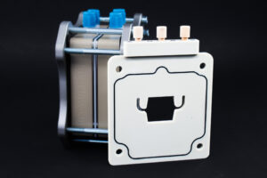
The accessory that unlocks multi-compartment CO₂RR on X-Cell hardware. The Chamber Insert is a chemically resistant polypropylene plate that drops into an X-Cell (and is compatible with the S-Cell and A-Cell) to add one central liquid chamber between the electrodes — or two, stacked, for a four-compartment build. Each insert carries its own reference-electrode port for thin Ø0.8–1.6 mm reference electrodes, so overpotential on the CO₂RR side can be measured directly against a membrane-adjacent reference. Standard 3 mm chamber thickness; custom thicknesses available by gasket choice or bespoke manufacturing.
All Redox-Flow CO₂ electrolysis cells are designed to operate as part of a complete laboratory platform. The most common additions for CO₂RR work:
Multiport Electrolyte Reservoir (250 / 500 / 1000 mL) for sealed, oxygen-free or CO₂-saturated electrolyte environments with integrated heating/cooling up to 95 °C. Hydraulic Connection Package (1/8″ or 1/4″) with PEEK unions, flangeless nuts and PTFE/Norprene tubing for low-contamination flow loops. Flow-Through Electrode Holder for inline reference-electrode, pH, ORP or conductivity measurement — and the primary way to measure CO₂RR overpotential on the three- and four-compartment cells described above. OCV Cell for decoupling anode and cathode overpotentials. Temperature Control Unit for stable operating-temperature studies. Full accessory list on the CO₂ Electrolysis Accessories page.
The baseline X-Cell in a zero-gap MEA build is the usual starting point. Pressing the GDE directly against the membrane minimizes ohmic losses and lets you push to higher current densities where gas-phase selectivity tends to improve.
Zero-gap puts the electrode against the membrane with no liquid in between — it’s optimized for low ohmic losses and gas-phase products. Multi-compartment deliberately places a liquid chamber between the GDE and the anode so that liquid-phase products can be collected and so the anode cannot re-oxidize them. The two architectures answer different research questions.
Yes. The X-Cell accepts 2.5×2.5 cm and 5×5 cm active areas on the same hardware by gasket swap, and it converts from 2-compartment to 3- or 4-compartment by adding Insert Chambers. The M-Cell Half Cell upgrades to a Full Cell by adding a second Half Cell plus a gasket set and an extra current collector.
Up to 90 °C across the range.