
DESCRIPTION: This cell is the same as X-cell (https://redox-flow.com/shop/x-cell/) except that it comes with additional ports that creates galvanic connections (Luggin capillary) to the inside of the cell for reference electrode measurements. Probably, there is no equal product on the market and the unique features of this X-cell are
This cell is a member of X-cells with additional ports (LINK) where the additional ports can be used for different purposes. I.e. if a X-cell with additional ports has been acquired it can be changed into the types only by buying the gaskets for that specific application. For a general description of the X-cell, please see X-Cell General electrolyzer. The X-cell with ports can be made for cells with ‘flat surface’ and interdigitated flow field current collectors. However, below it is only described with flat surface below.
GASKETS & ELECTRODE THICKNESS: Due to the many variations, cells are sold without gaskets that has needs to be ordered individually and is described below.
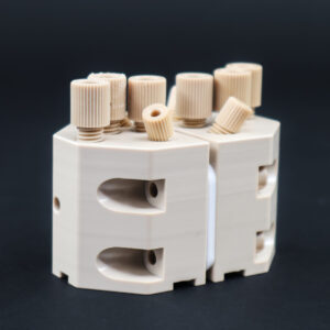
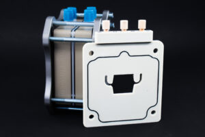
Flat current collectors: The main components of this configuration is shown in the image below – (Click on picture to get higher resolution)
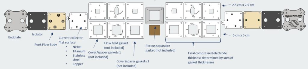
Cover/Spacer gaskets – Here two different cover/spacer gaskets are needed (shown below)
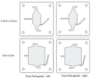
Flow field gaskets – Here two different flow field gaskets are needed (shown below) – note that they are similar but are not symmetric (like almost other Redox-Flow gaskets)
Membrane/Separator gasket – Optional, only needed for porous separators to prevent leaking out through the side of the porous separator.
GENERAL DESCRIPTION
The cell has been developed for Alkaline water electrolysis, Anion exchange membrane water electrolysis (AEMWE), PEM electrolysis and CO2 electrolysis, but can be used as a general electrochemical flow cell e.g. fuel cell, non-aqueous electrochemical systems etc. This is also reflected in the many standard material options that are available for the cell.
Besides the current collectors and electrodes the electrolyte will only be in contact with corrosion resistant polymers which is important to ensure that e.g. electrodes/catalysts are not poisoned from dissolution of e.g. metals in the cell. Also it can be operated in the full pH range (depending on materials choices) and to elevated temperatures (95°C).
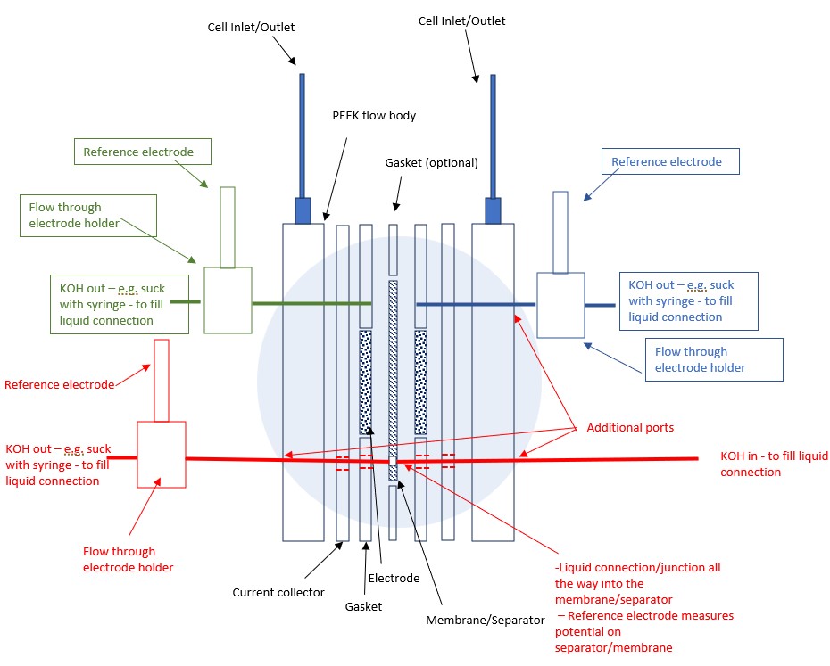
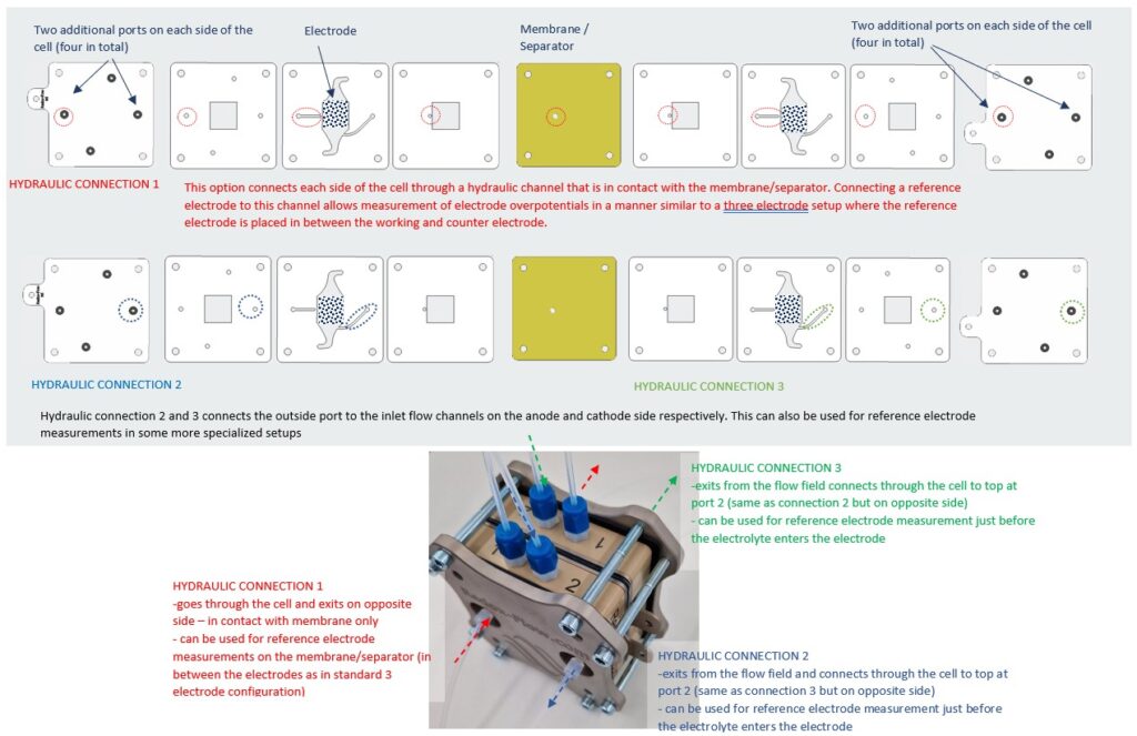
This cell is a variant of the X-cell, the main difference being additional ports for a (reference) electrode that is coupled, to measure on the separator/membrane, through a Luggin capillary type setup. The figure below is a schematic overview of the working principle. Red parts are reference electrodes and the hydraulic circuits of these, while blue parts are the X-cell. The reference electrodes at the top can be connected through a T piece (and are not in scope in this manual).
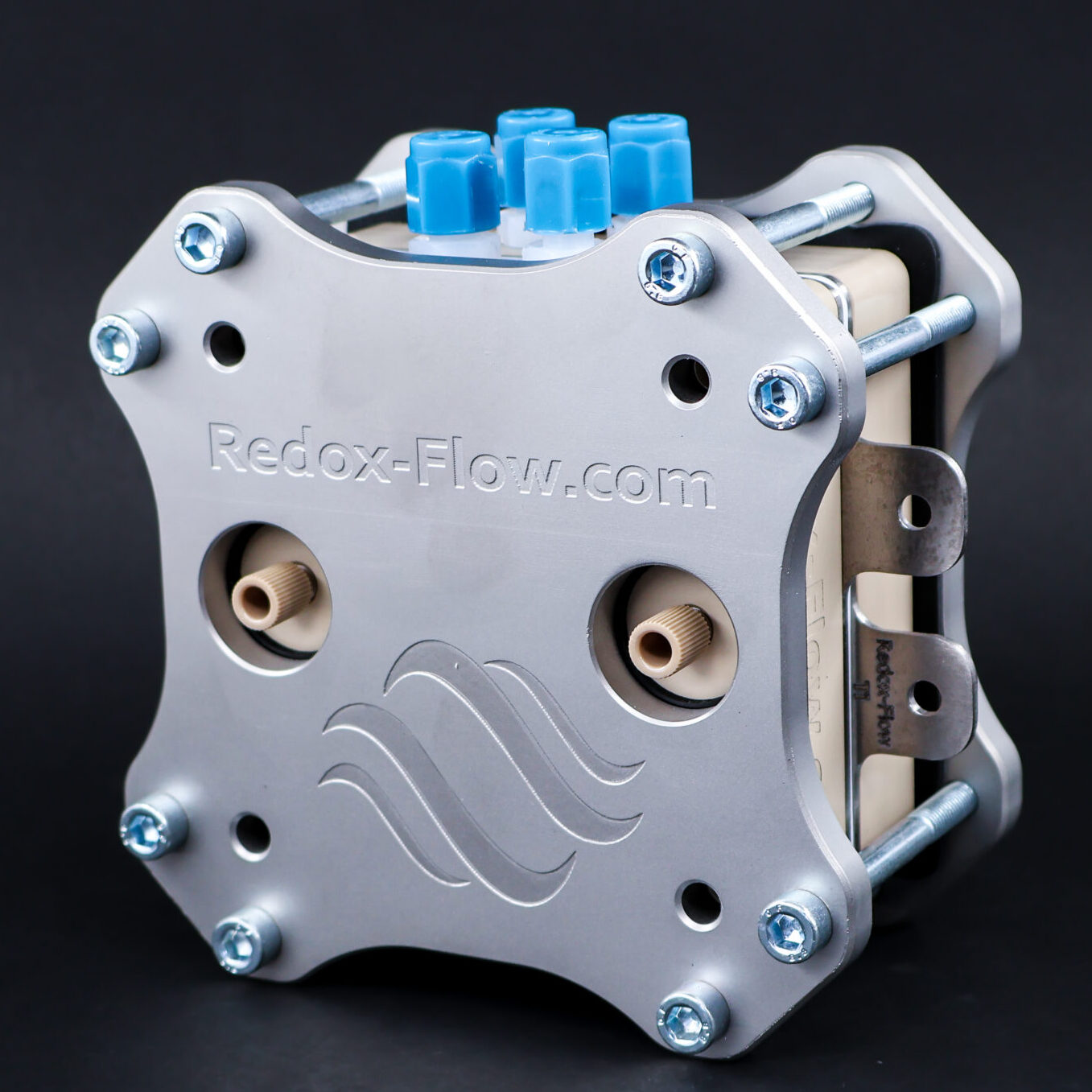
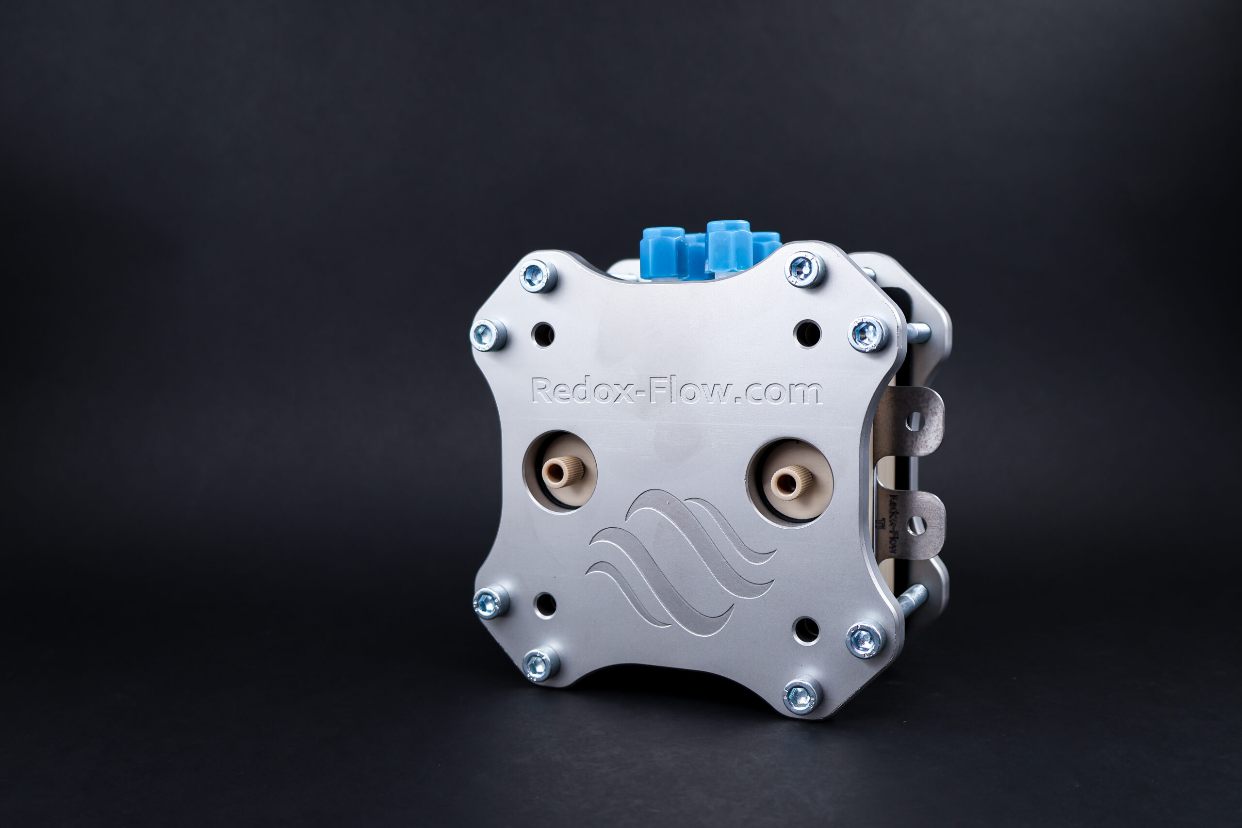
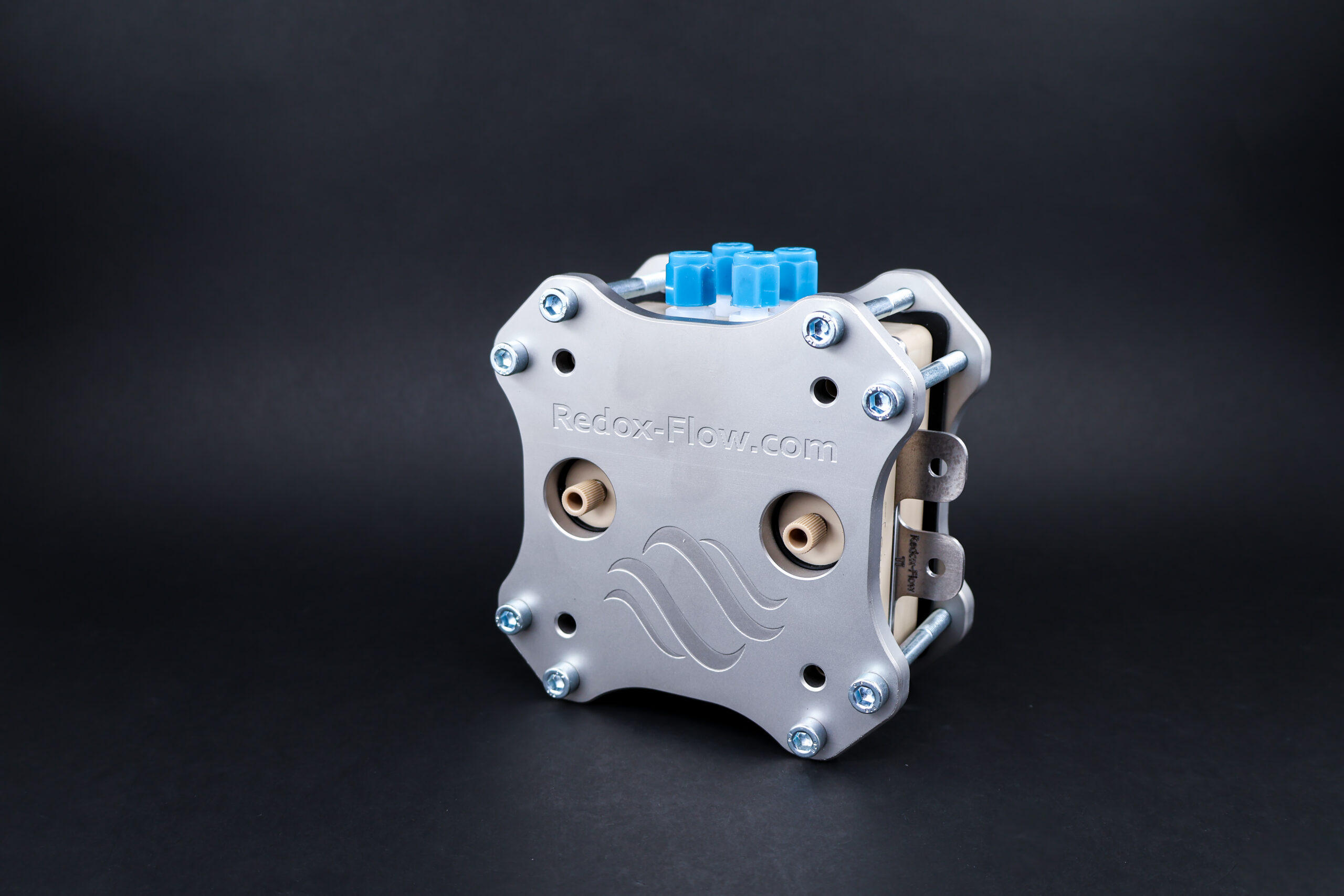
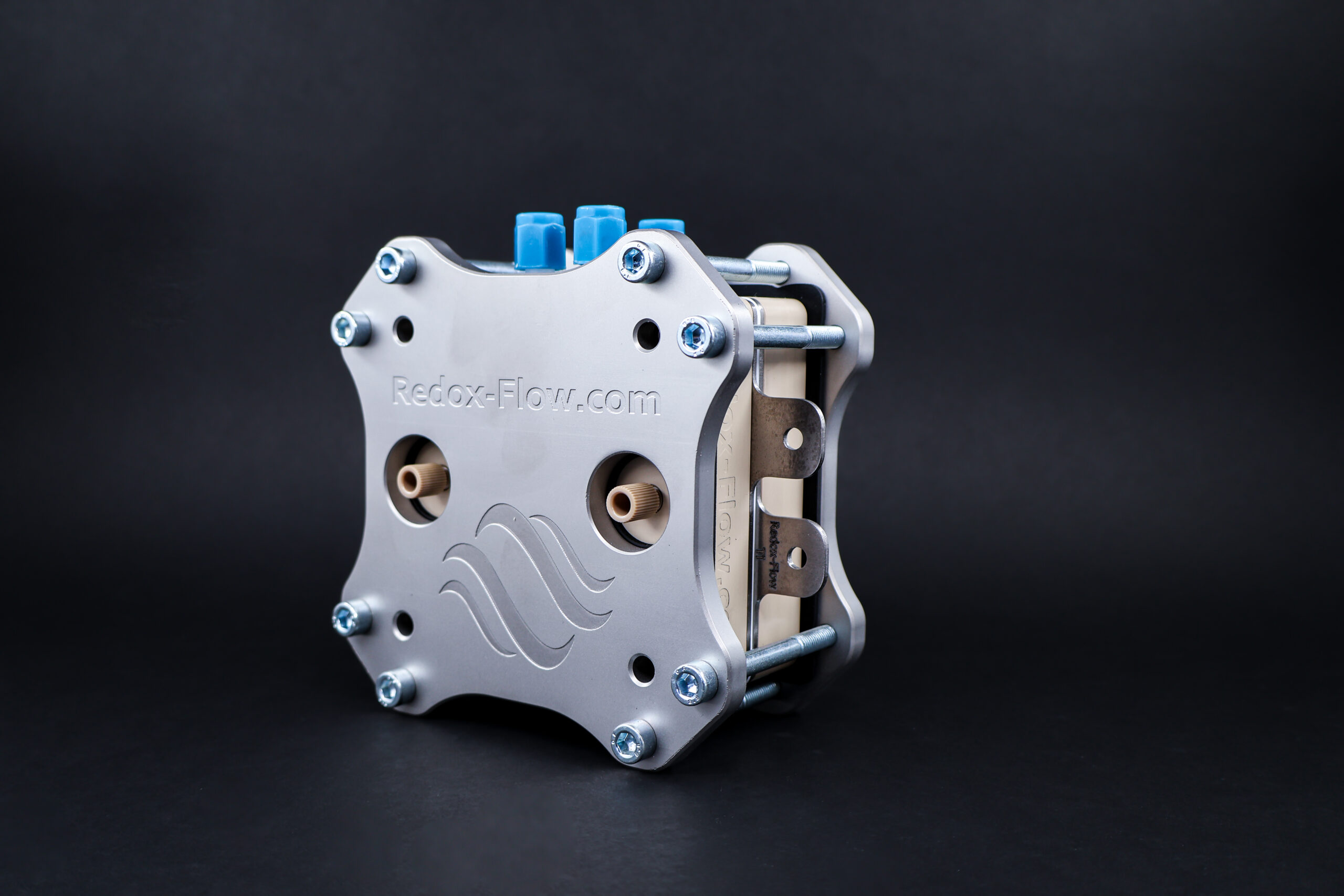
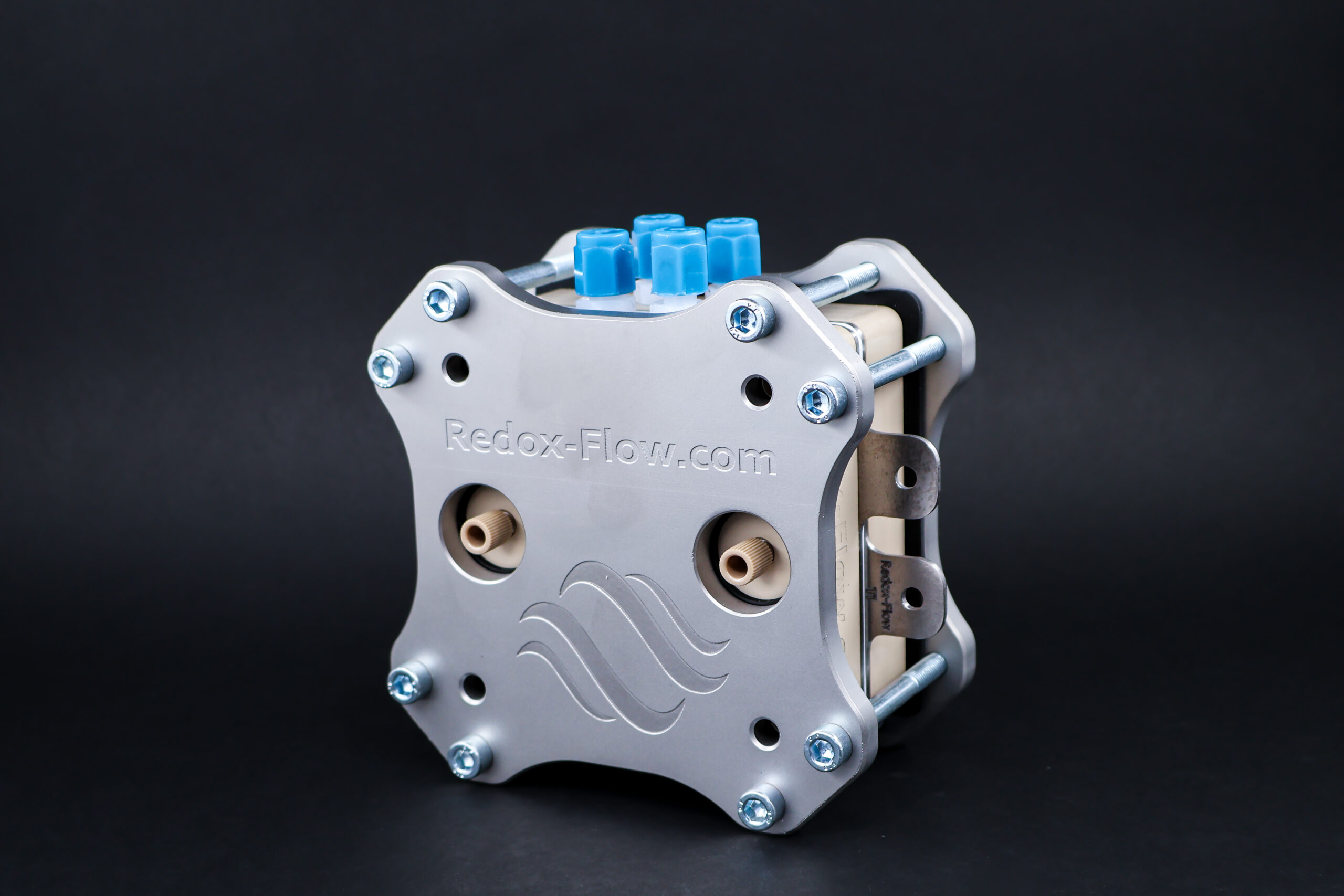
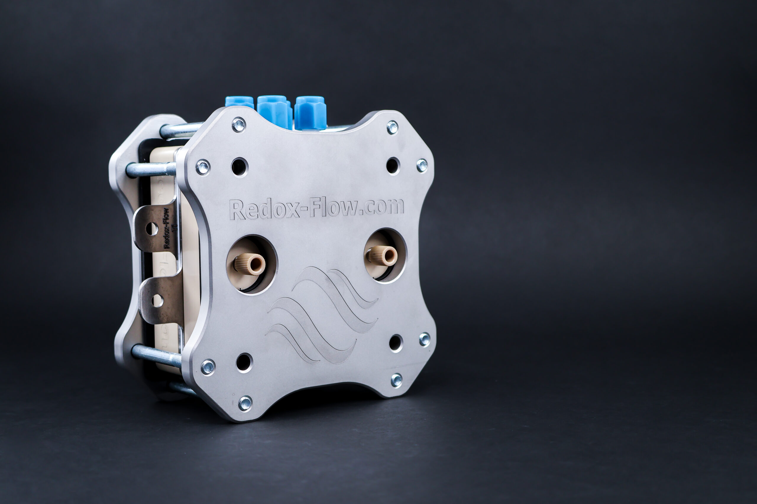
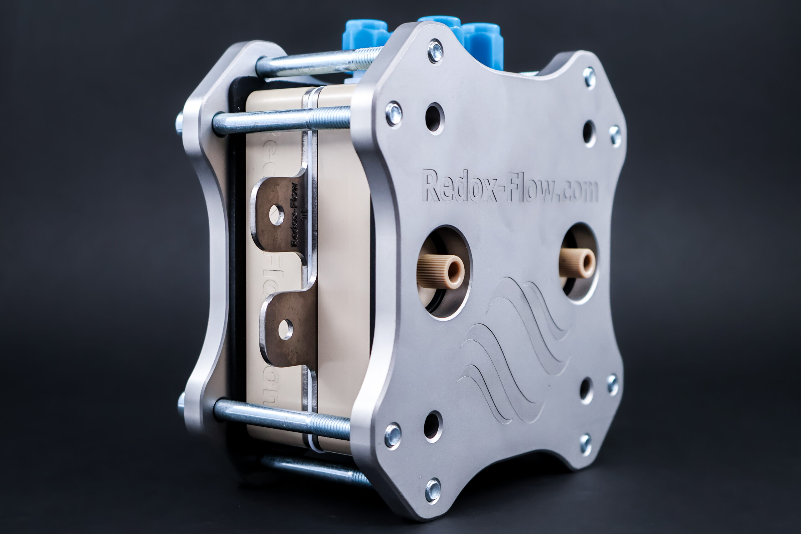
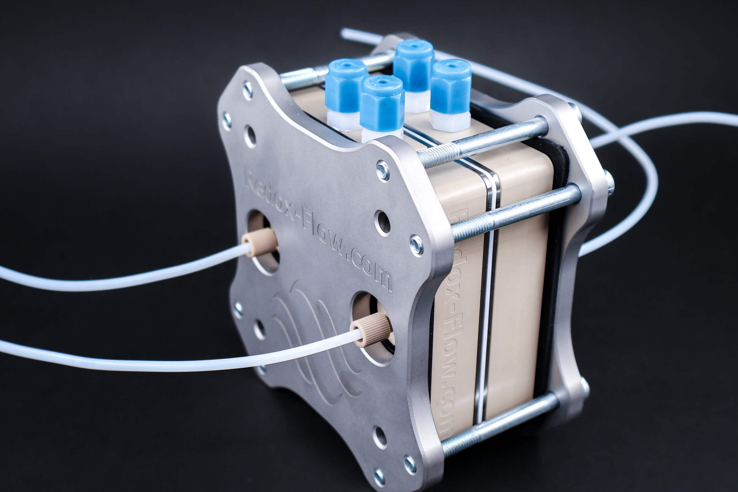
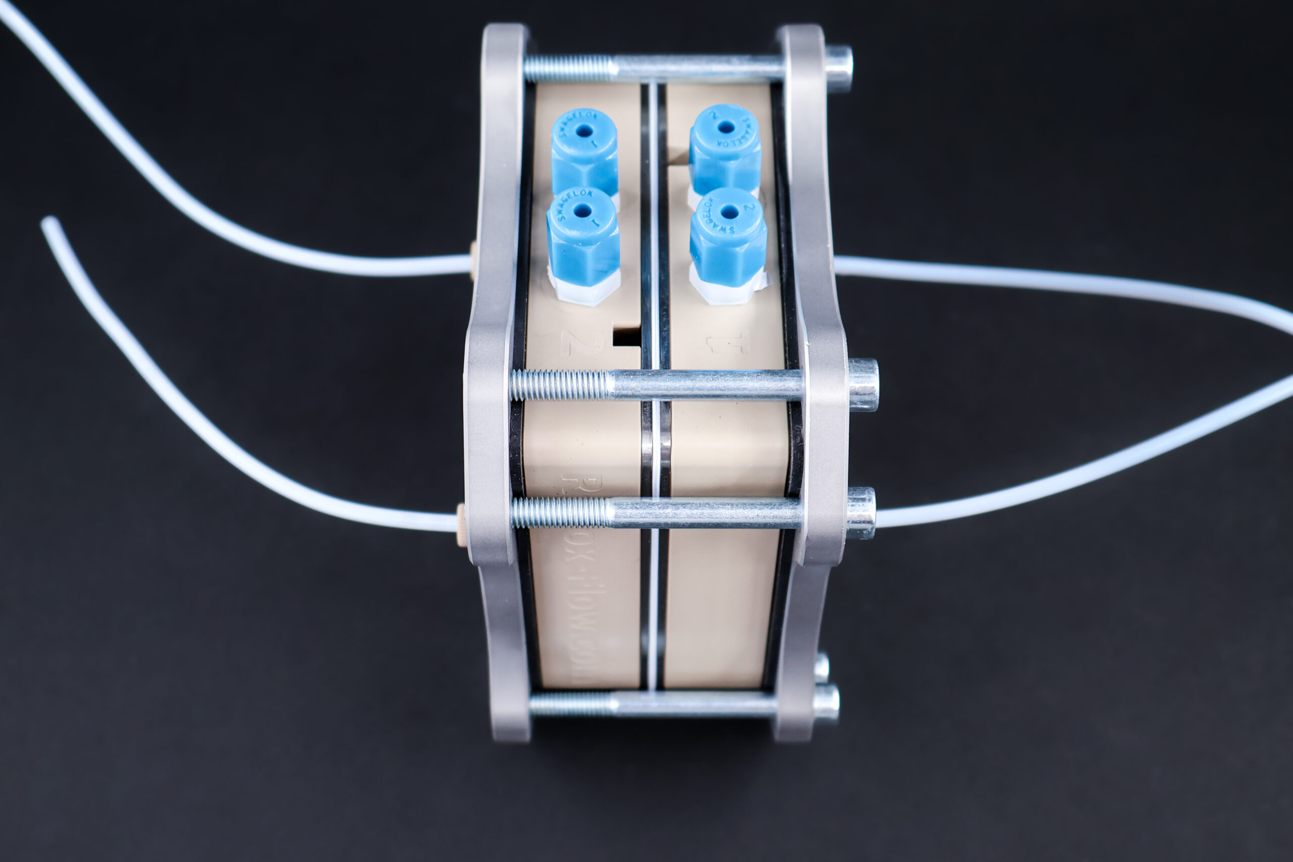
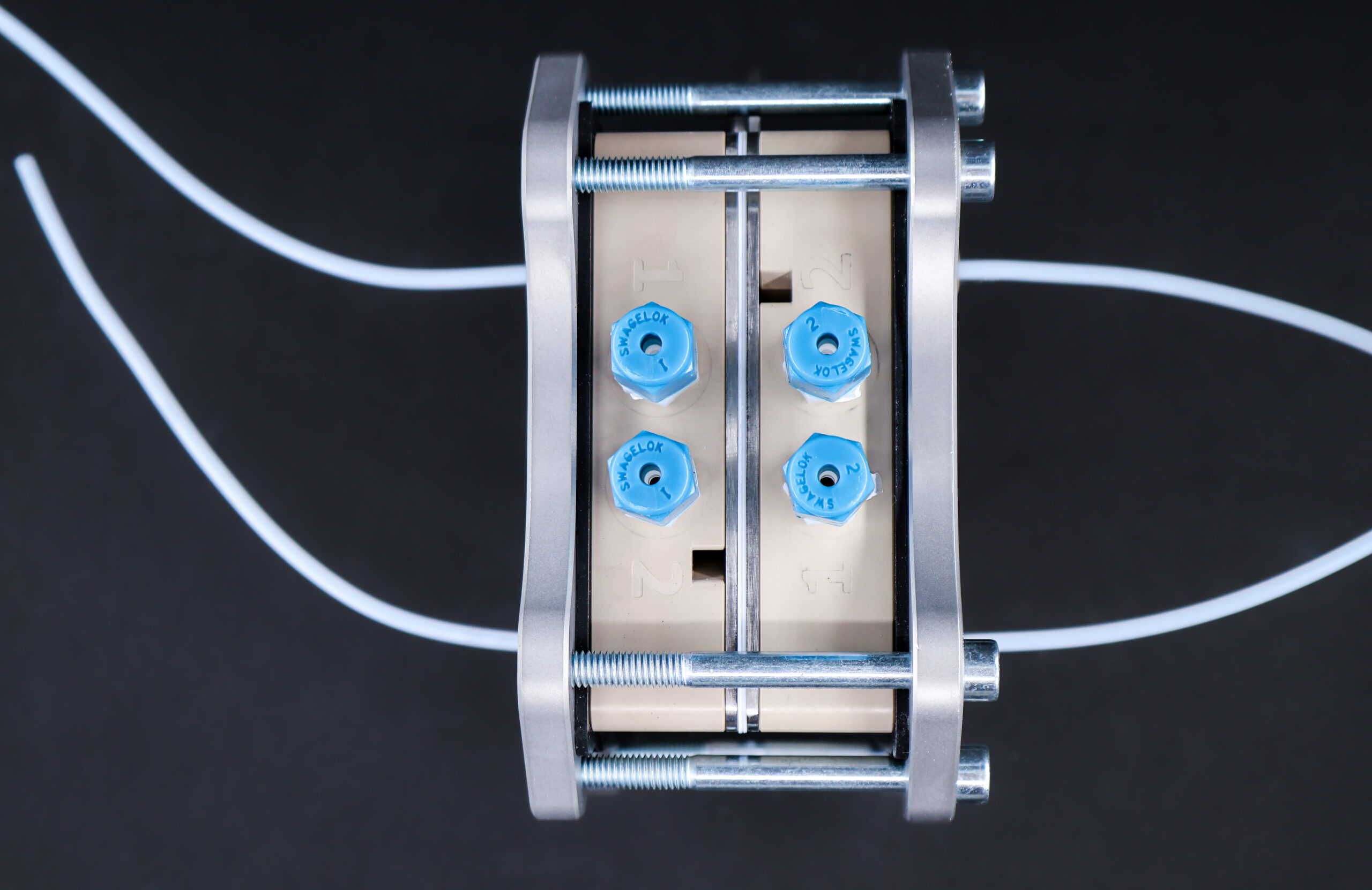
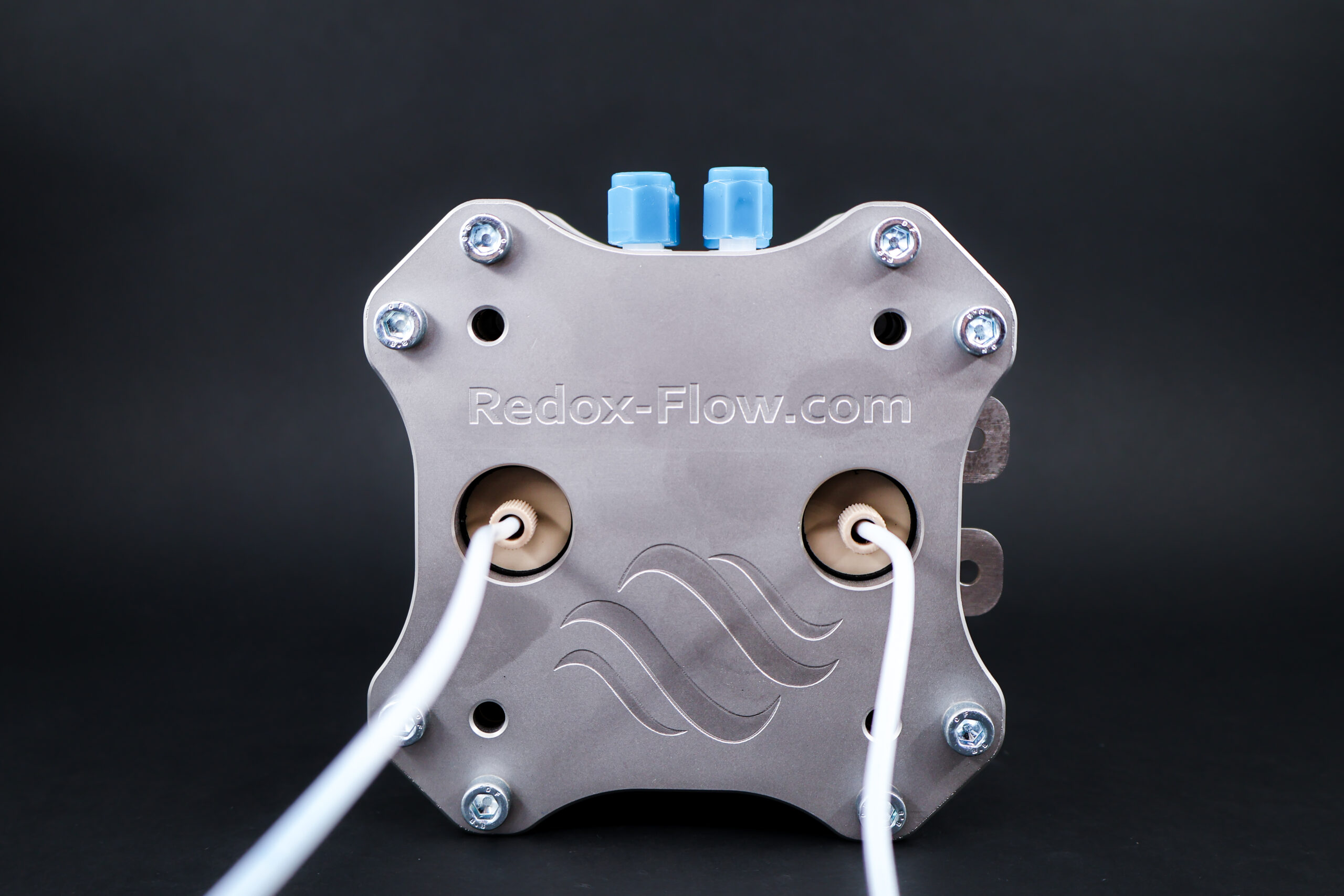
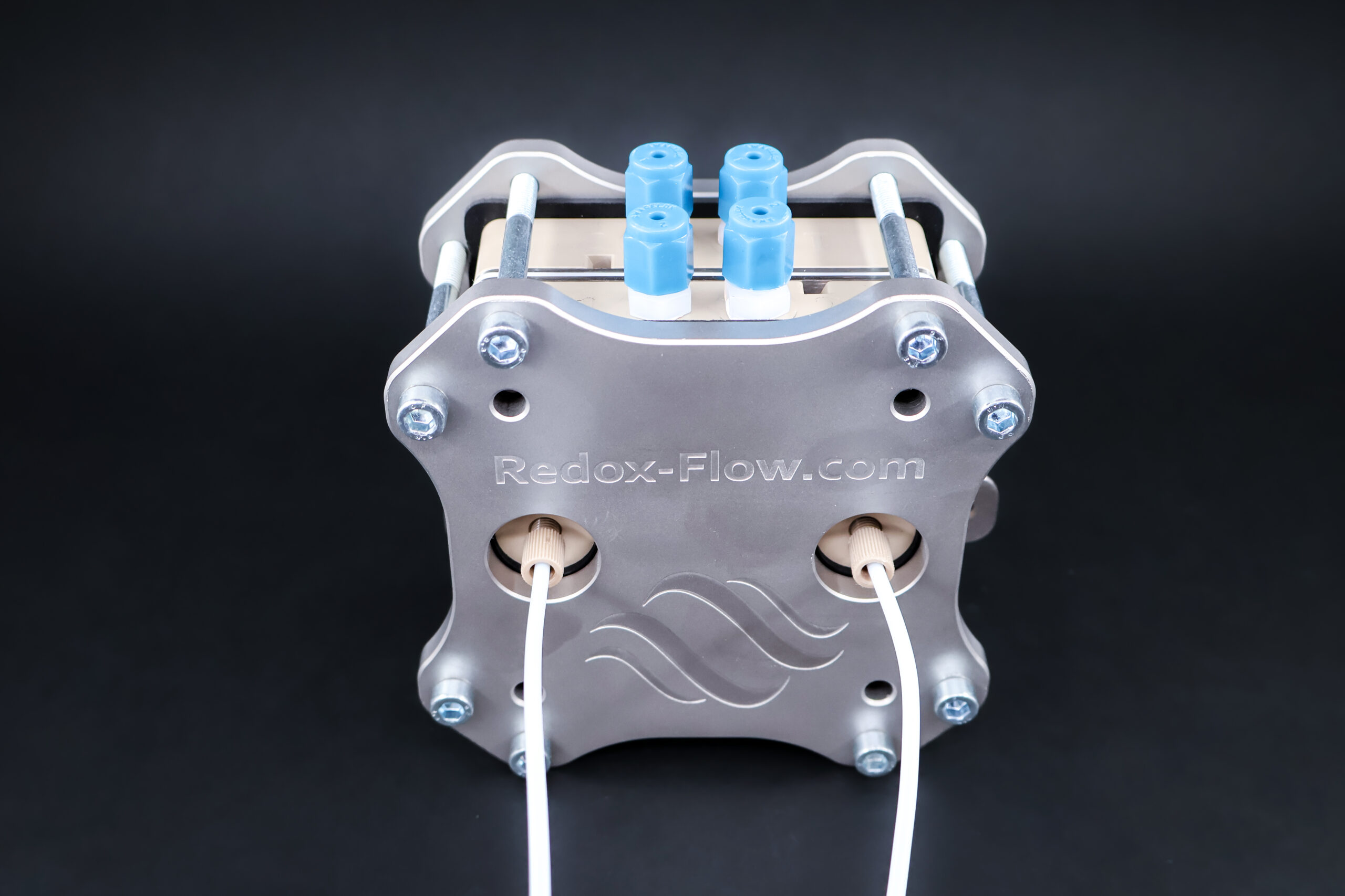
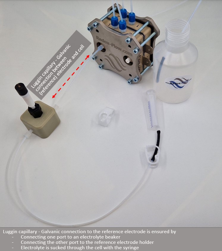
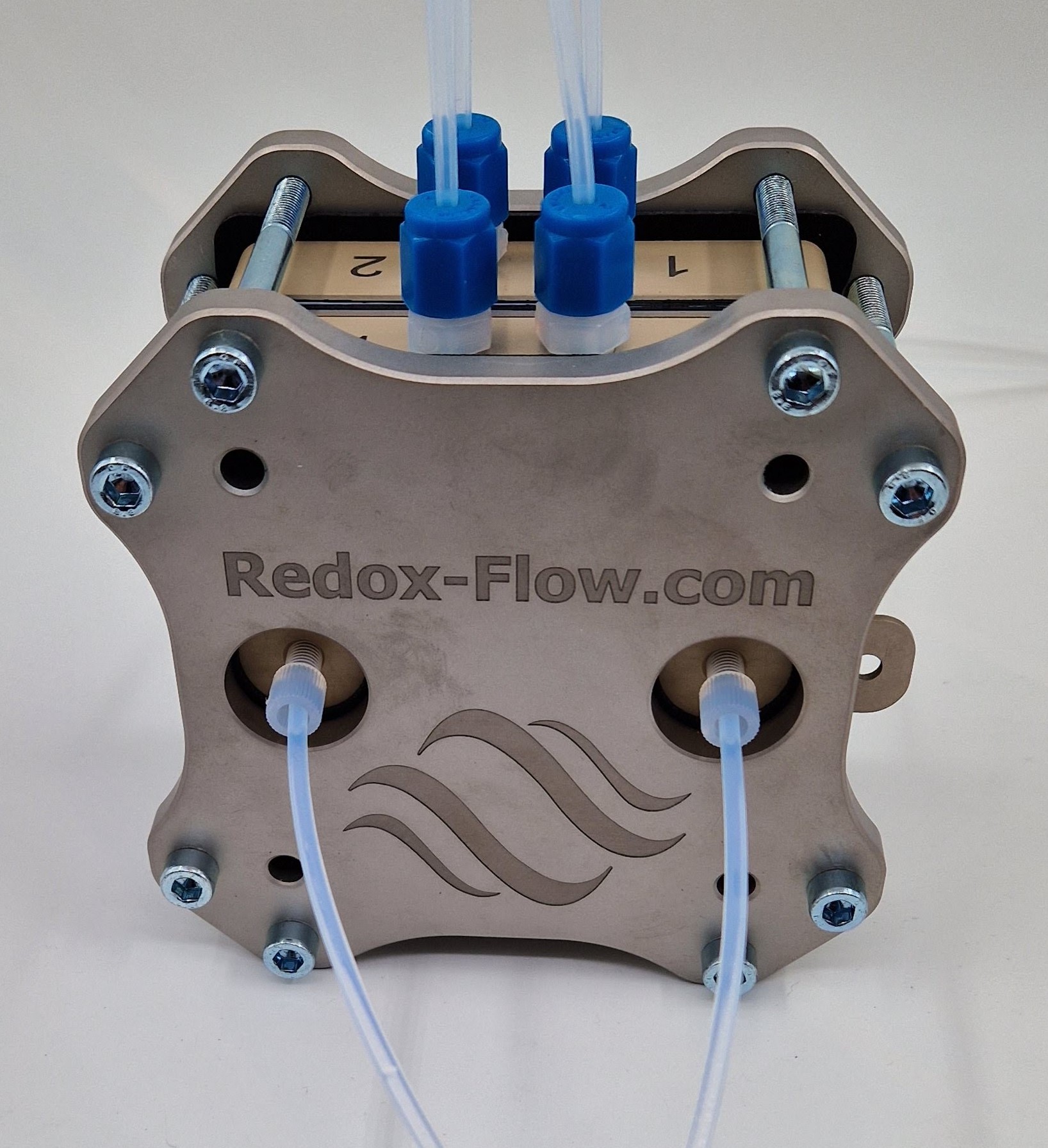
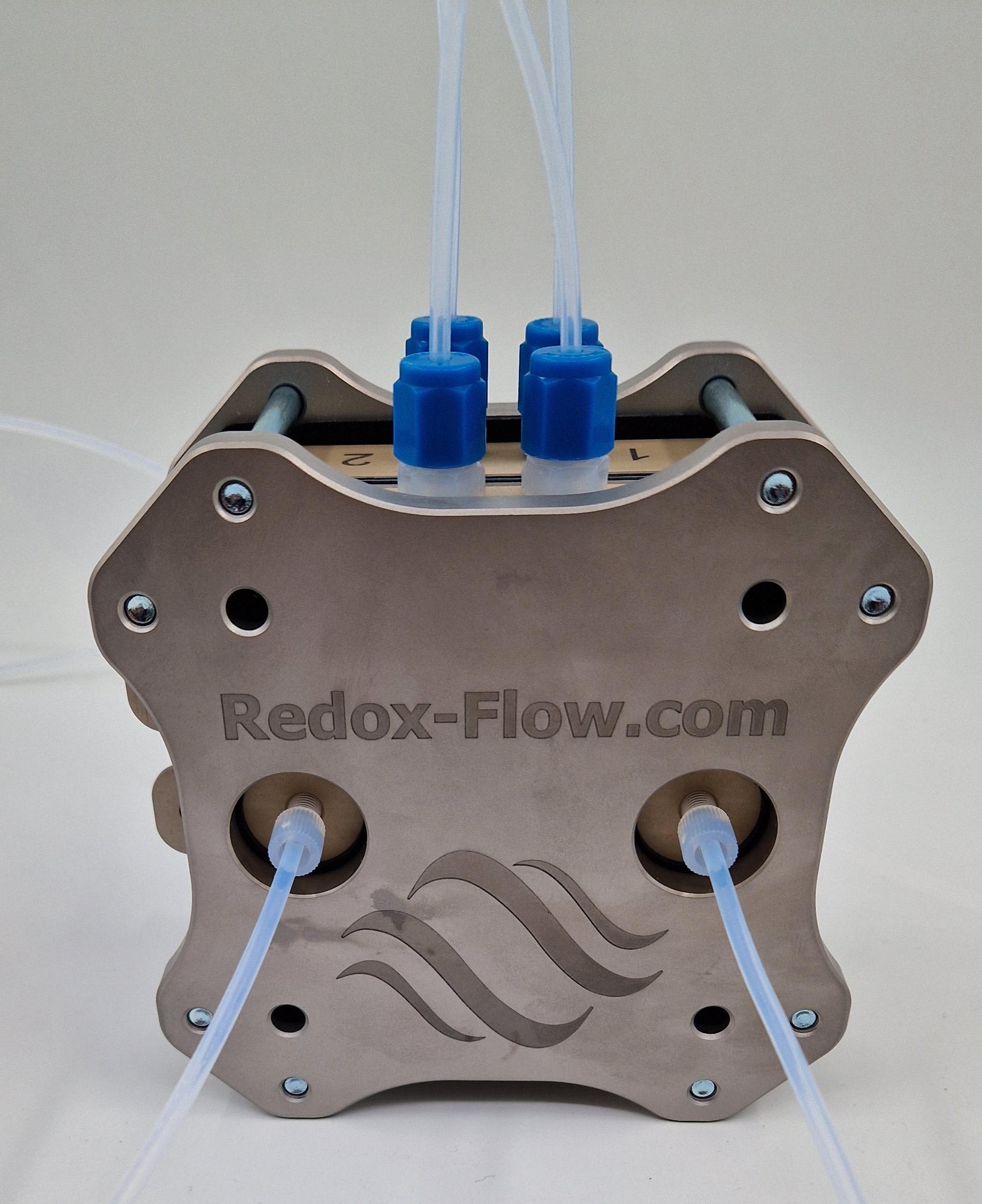
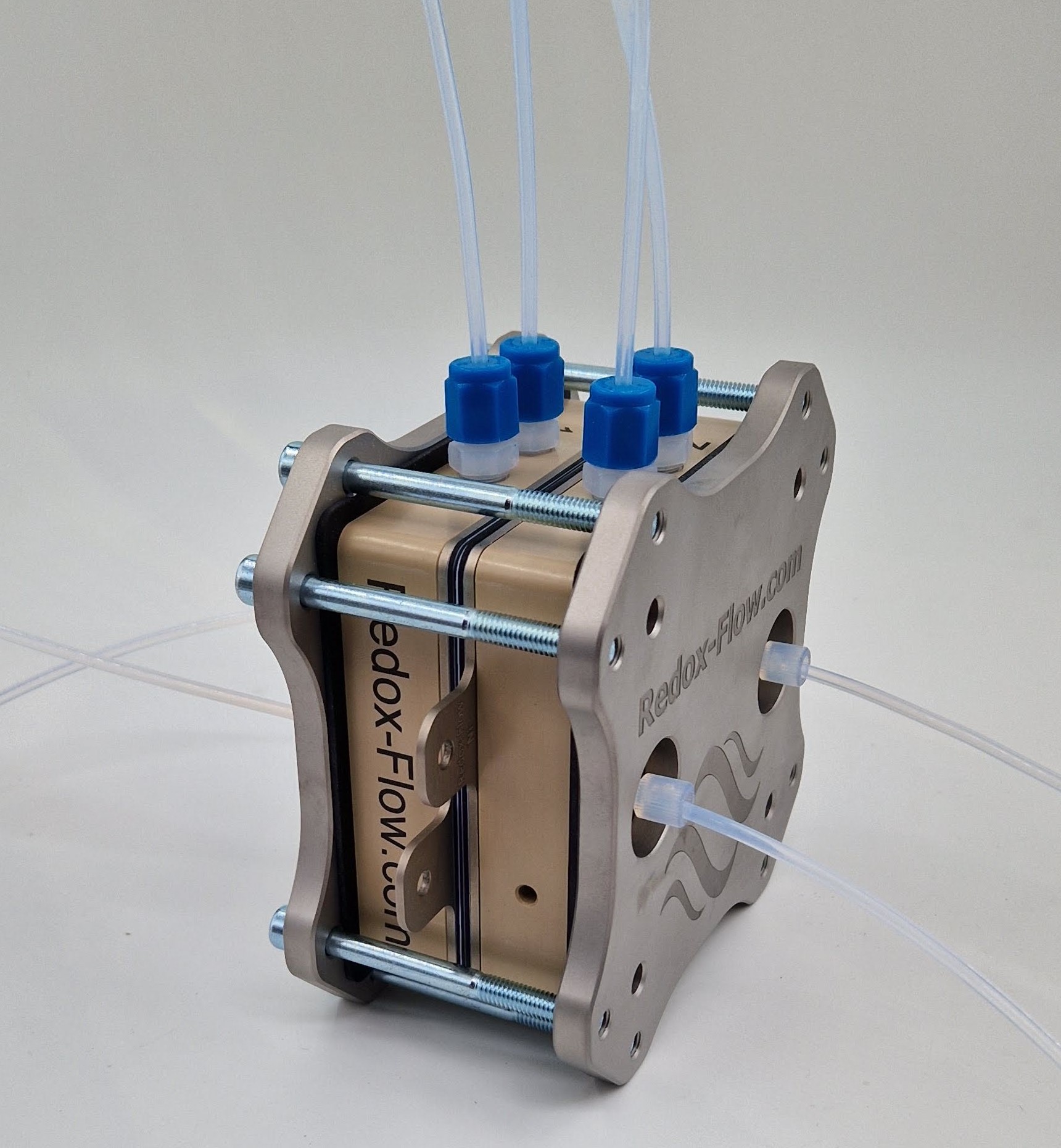
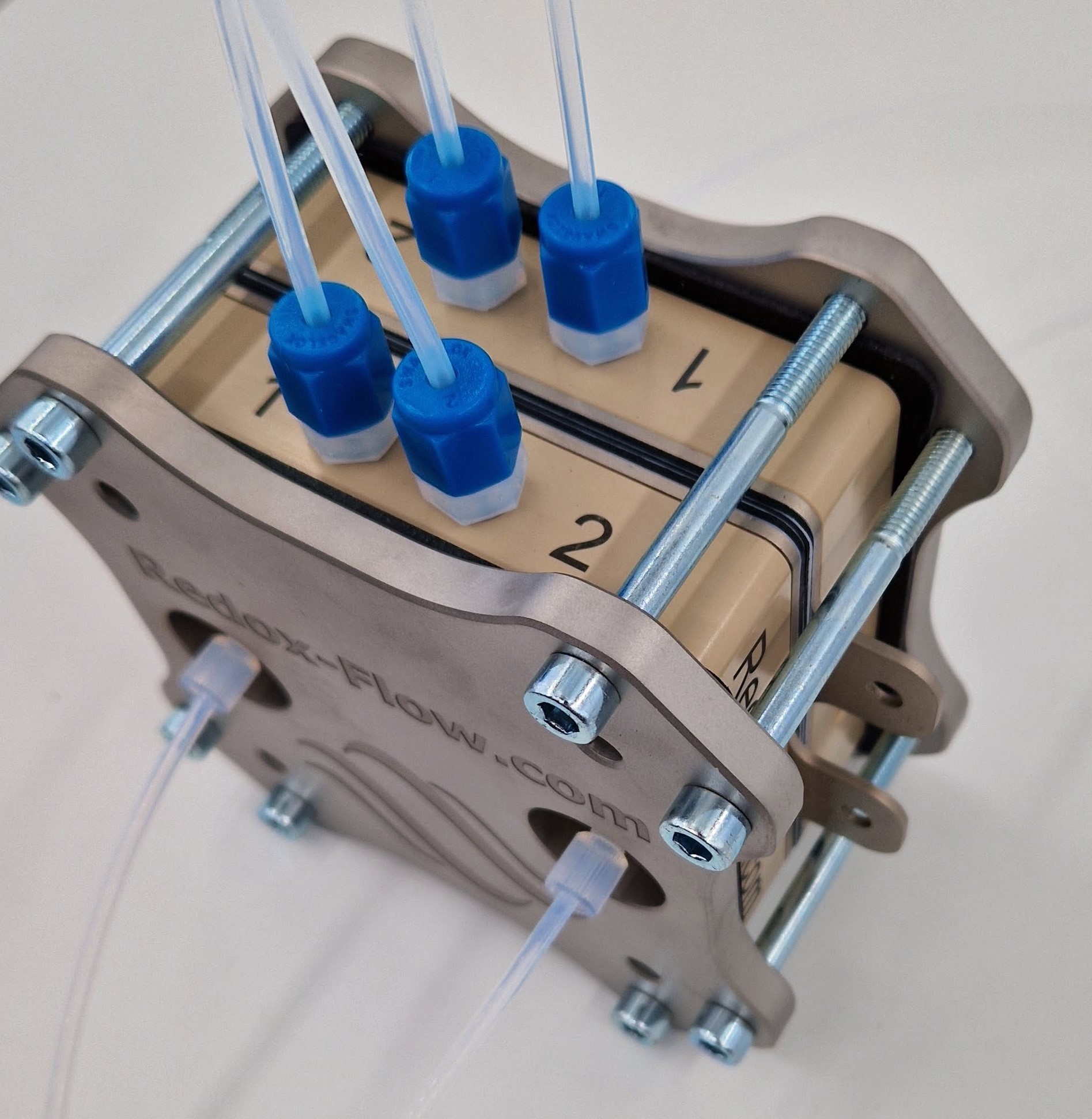
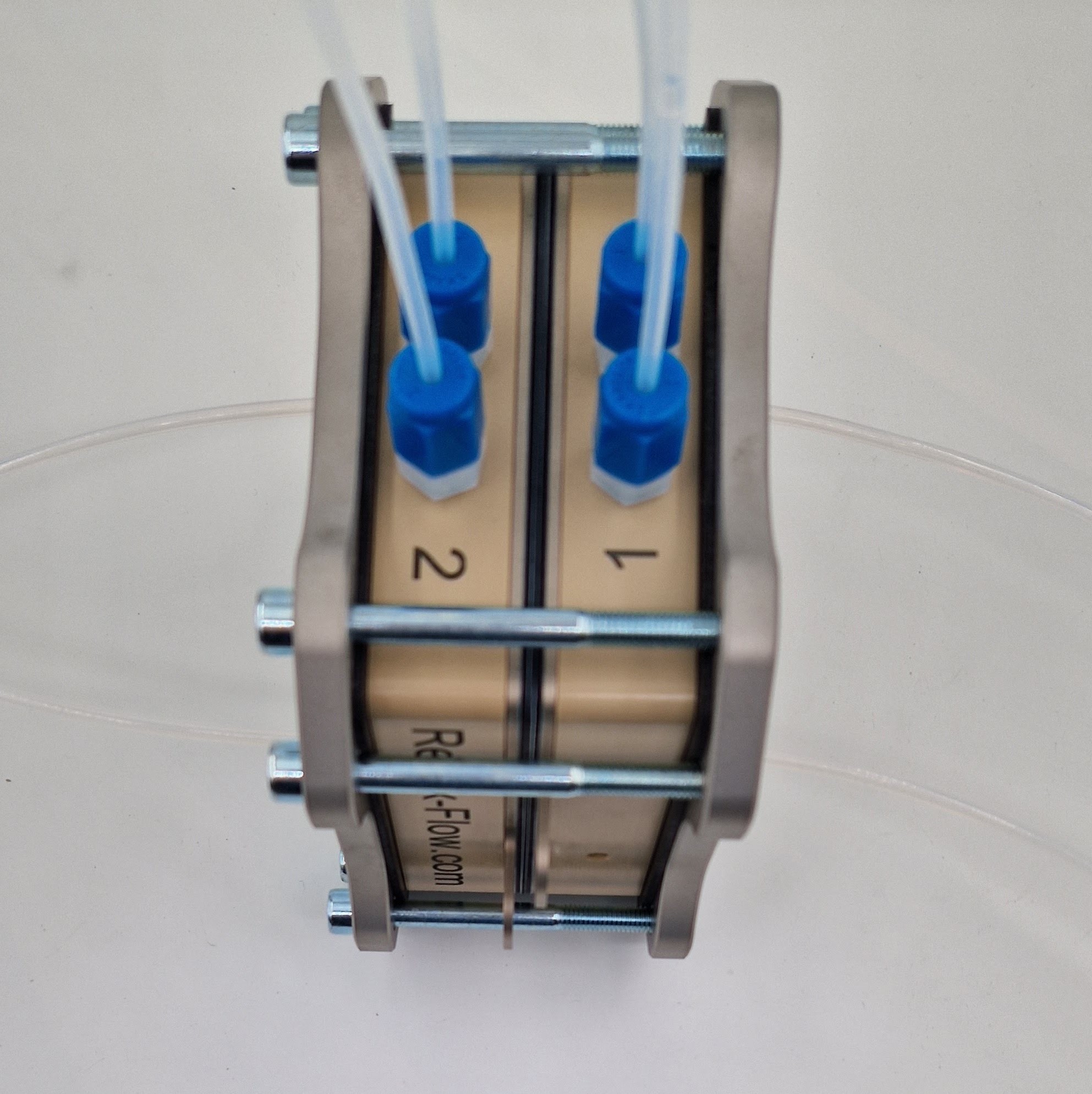
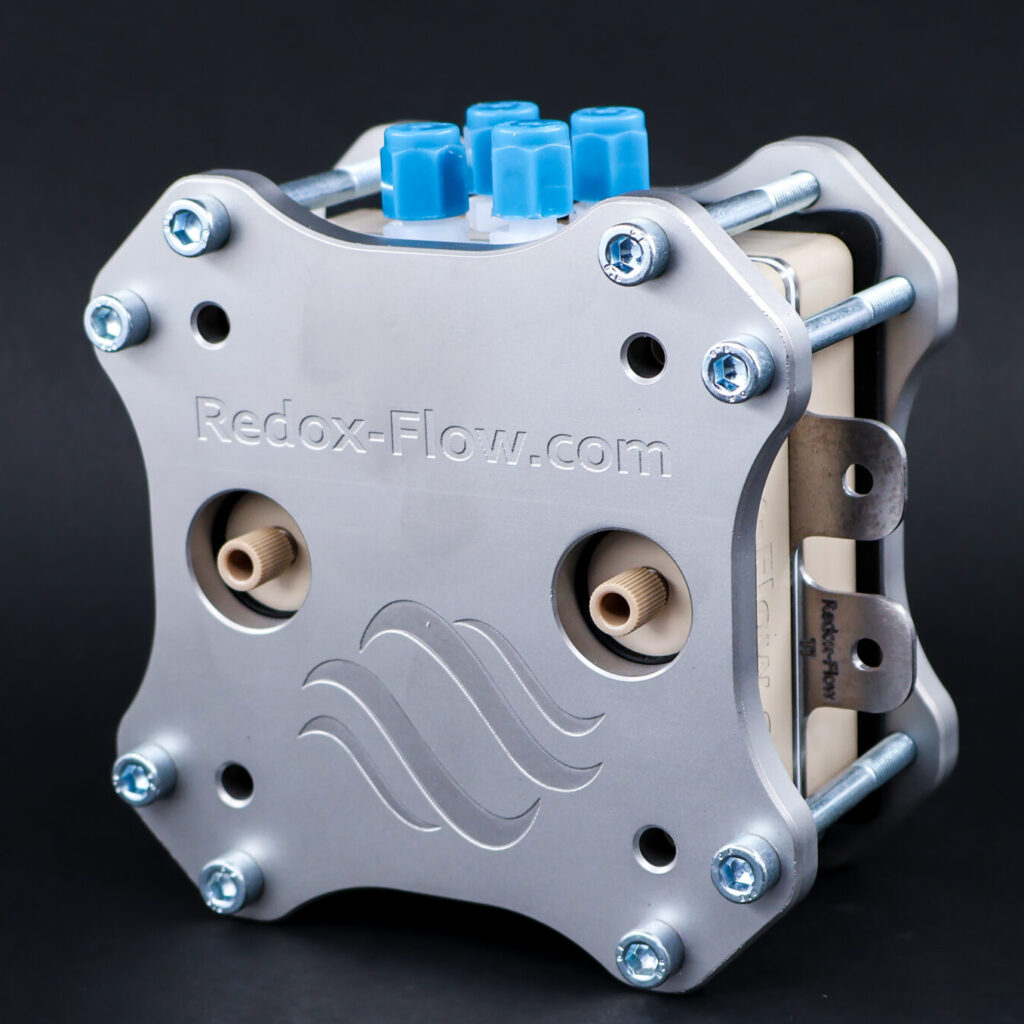
The main difference between the standard X-cell and the one is highlighted by the blue shaded round area. Here additional ports on each side of the cell are included. This enables a hydraulic connection to (i) the separator/membrane which can be used for a reference electrode measurement (Luggin capillary type) and (ii) electrode inlets on both the cathode and anode side. To ensure a unbroken galvanic connection between the separator/membrane there are ports on each side. One is used for a reservior (rigth side) while the left side is connected to the reference electrode (e.g. through the Redox-flow ‘Flow Through Electrode Holders’. The galvanic connection is obtained by sucking electrolyte through the ports with a syringe (see photos below)
Overview of the function of the different gaskets and holes is shown below.
The cell works excellent together with our Flow Through Electrode Holder (see image below)

PERFORMANCE DATA
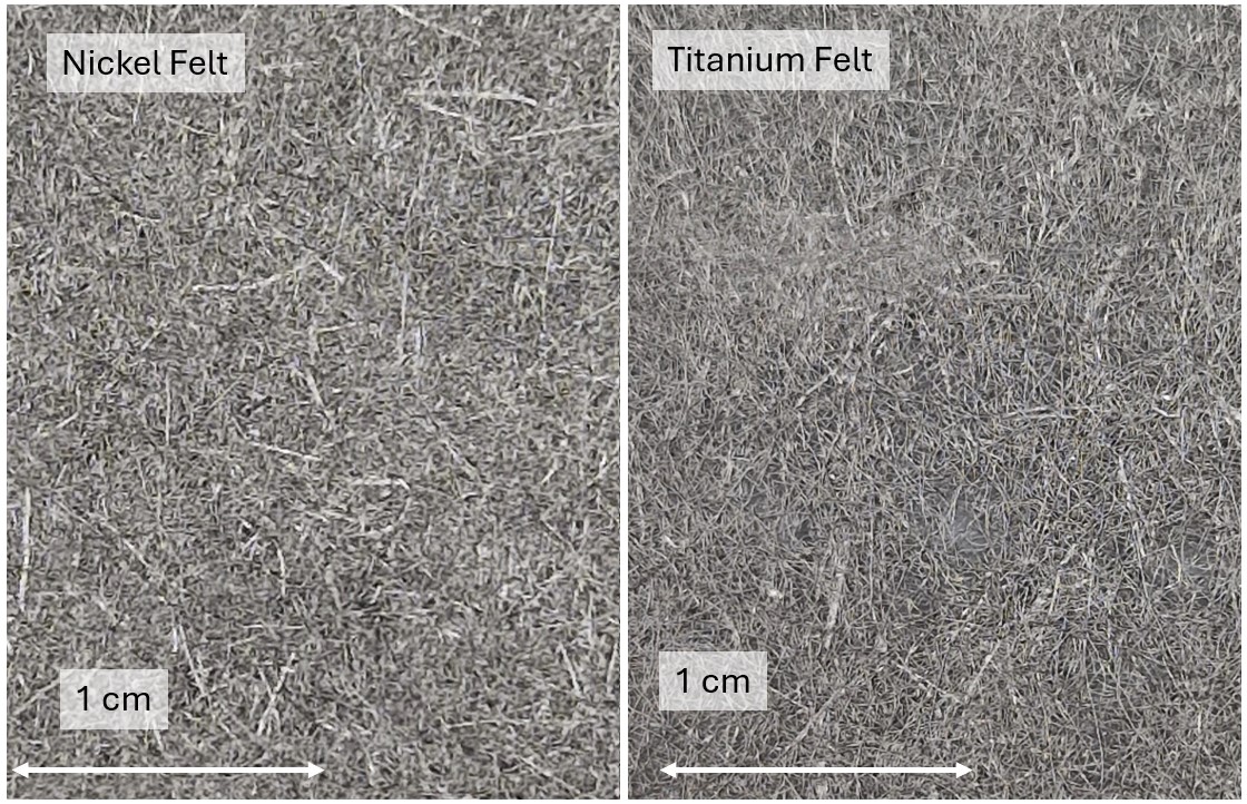
Figure below shows the polarization curve for a setup with nickel foam electrodes, 6 M KOH measured at room temperature. Here an area specific resistance of about 1.1 Ωcm2 is found and the activation voltage is about 2.2 V. This is similar to the values found in litterature recorded under similar conditions, thus the ‘relatively’ poor performance is because of the low temperature and that the electrodes are untreated (no catalysts). Thus much better performance can be obtained with higher temperature, thinner separator and treated electrodes.
The right side shows the overpotentials measured through the four ports in the cell in a Luggin capillary configuration that is the same as in the figure above with a Hg/HgO reference electrode for each of the three luggin capillaries. The graph shows the maximum and minimum overpotentials, that are measured versus the membrane and in the liquid just before entering the electrodes, respectively. All potentials are not IR compensated and the definitions follows the ones in this paper. Besides the fact that the electrodes are outside the cell and the cell thereby can be operated at high temperature without destroying the reference electrodes, another unique feature is that luggin capillares just before the electrodes are placed within a few mm of the electrodes. This has the positive effect that the IR compensation becomes very small or even close to negligible under many circumstances.

CDI Flow Cells, CO2 Electrolysis Cells, ...
From: 1,955.00 €
CDI Flow Cells, CO2 Electrolysis Cells, ...
From: 1,395.00 €
CDI accessories, CO2 Electrolysis Accessories, ...
2,395.00 €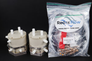
CDI accessories, CO2 Electrolysis Accessories, ...
1,950.00 €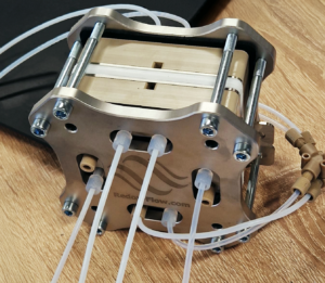 From: 5,545.00 €
CDI Flow Cells, CO2 Electrolysis Accessories, ...
795.00 € This product has multiple variants. The options may be chosen on the product page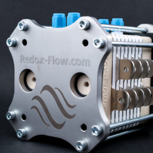 From: 4,151.00 €
 From: 7,106.00 €
 From: 7,849.90 €

CDI Flow Cells, CO2 Electrolysis Cells, ...
From: 3,320.00 €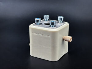
CDI accessories, Electrolysis Accessories, ...
485.00 €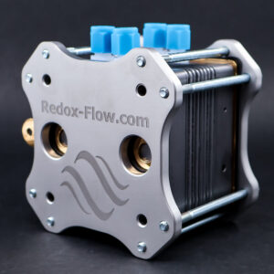 From: 3,410.00 €
 From: 3,395.00 €
CDI Flow Cells, CO2 Electrolysis Cells, ...
From: 2,826.00 €