
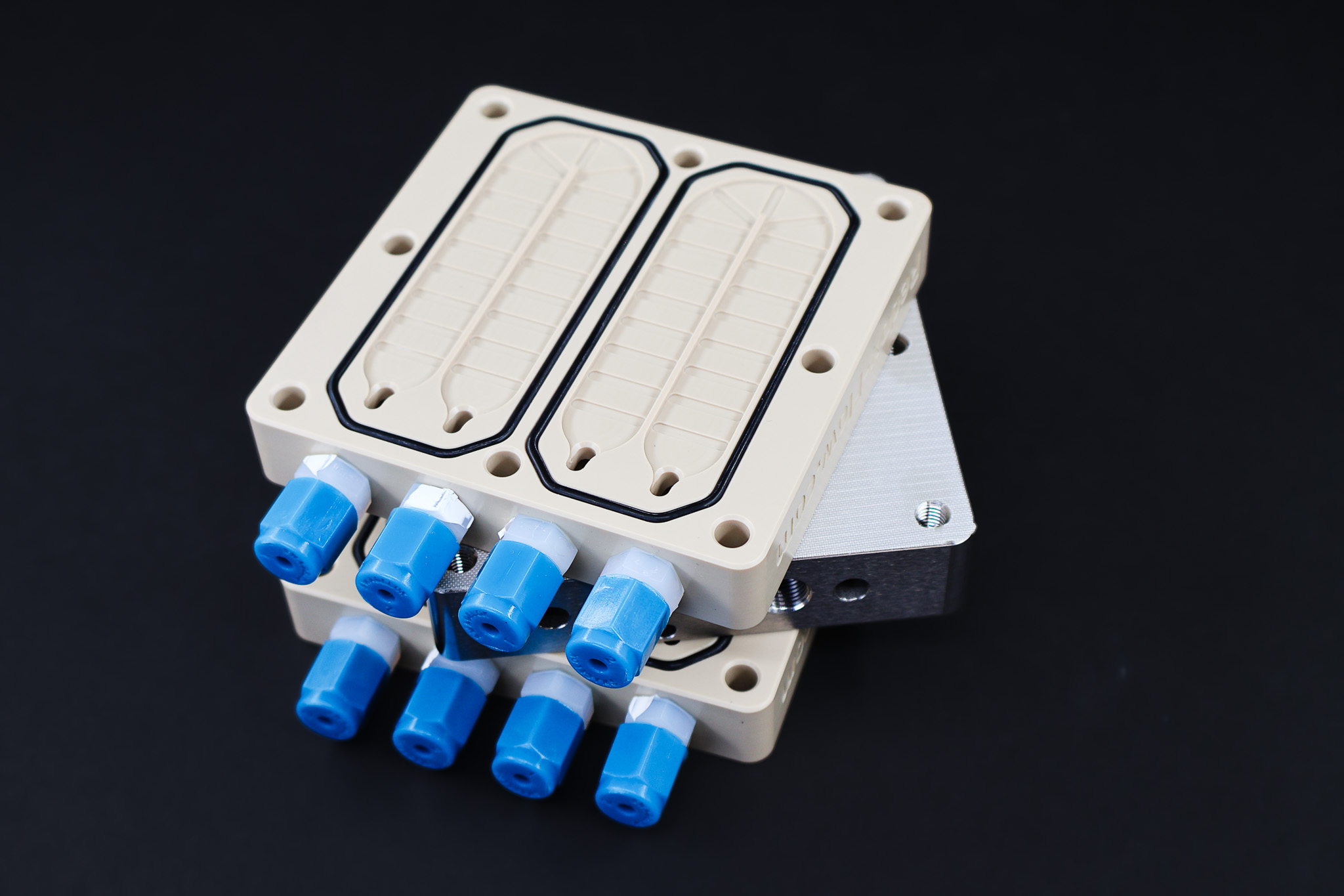
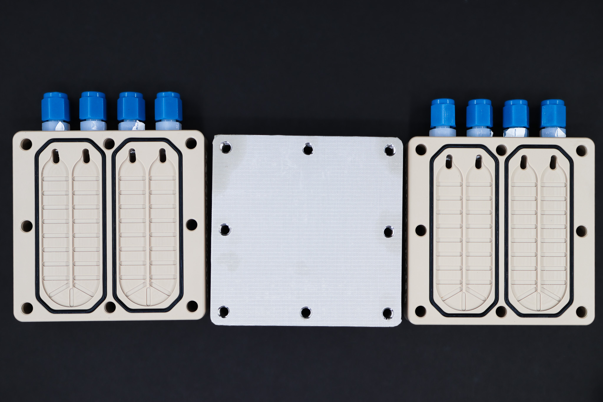
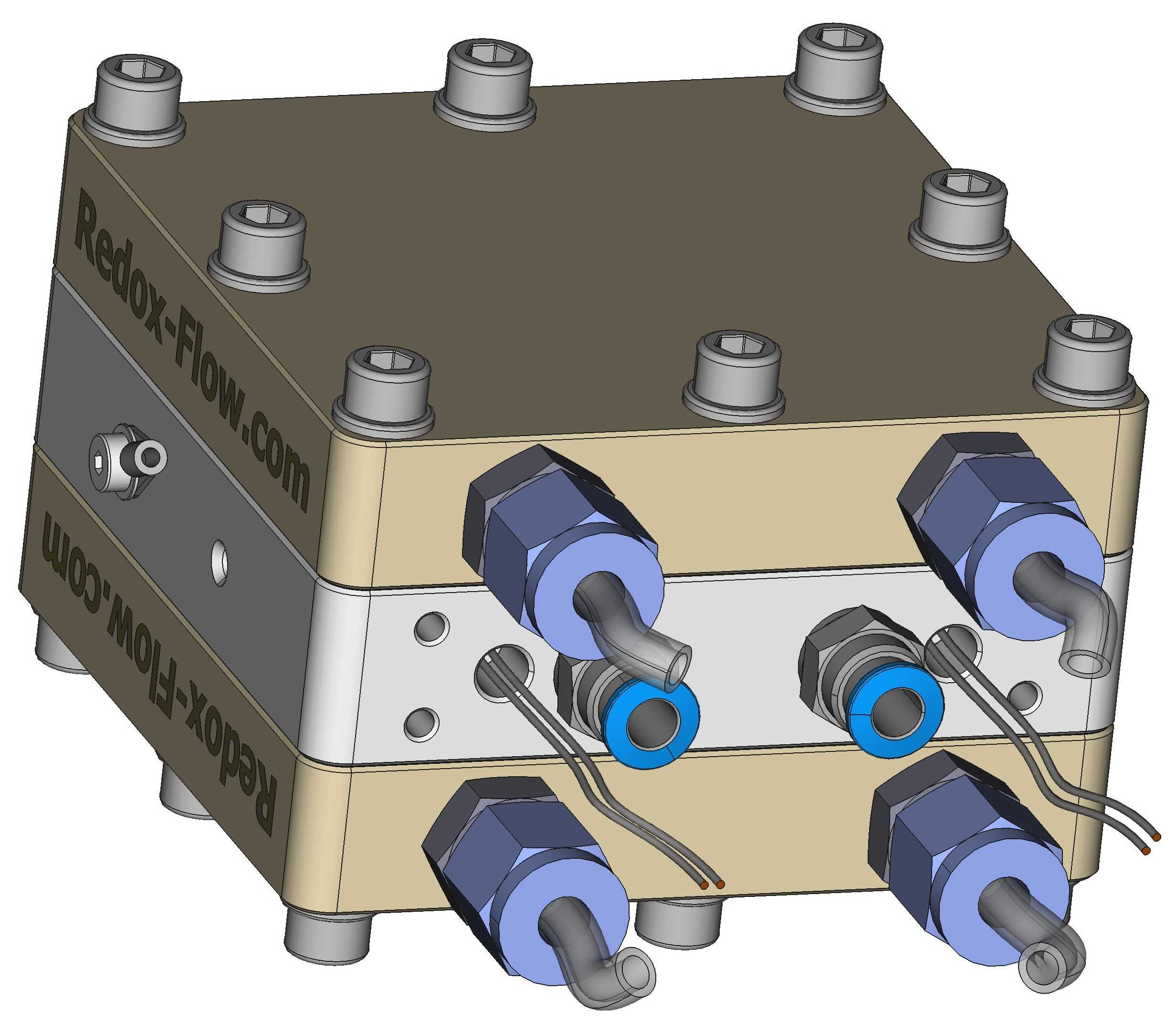
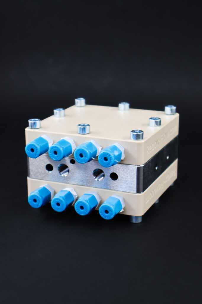
Shown in the figure below, two PEEK flow bodies sandwich an stainless steel block and heats/cools the circulating electrolytes in both PEEK flow bodies. The stainless steel block is protected by a thin PTFE sheet to prevent corrosion of the stainless steel.
The stainless steel block is heated by either heat cartridges (not included) inserted into the stainless steel block or heated/cooled by heating/cooling water circulated in the stainless steel block.

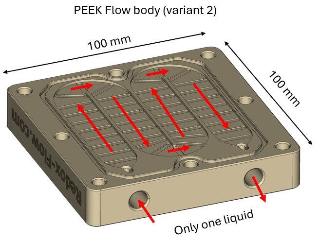
The two PEEK flow bodies only has one heating channel each, however, combined the two PEEK flow bodies can heat two independent electrolyte streams. Alternatively if only one electrolyte stream is heated, they can be coupled in parallel. This option is recommended for stacks other applications where higher heating or cooling power is needed.
Assembly manual
Performance data
Due to the many configuration of this unit all options have not been tested. Nonetheless the data below shows the general performance of the unit.
Heat transfer coefficient
Graph below shows the heat transfer coefficient between the metal block and the liquid. It is measured by heating about 500 mL of water in a bottle (without an electrochemical cell) by placing the heating unit on a heating plate where the metal block temperature is fixed and the temperature in the bottle is monitored.
The heat transfer coefficient is in the range 1 W/K to 5 W/K and dependent on the flow rate. We term the coefficient ‘apparent’ as it is does not strictly follow the definition of the ‘overall heat transfer coefficients’. Nonetheless, the coefficients can be used for estimating the heat transfer power between the unit and the liquid. I.e. if there is a 40 K temperature difference between the metal block and the liquid and the flow rate is 100 mL/min it can be expected that 100 W of heat is transferred.
![]()
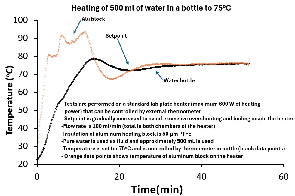
Bottle heating
Graph below shows a configuration where the unit is placed on a heating plate and connected to a pump and a bottle with 500 mL of water (i.e. an electrochemical cell is not included in the circuit). The heating plate has maximum 600 W heating power and PID control, where the input for the control is an external thermometer, which in this case is placed in bottle. In addition to this thermometer, one is also placed inside the metal block. In this test, the water temperature set-point in the bottle was set at 75°C. It is seen that the water reaches 75°C within 15 minutes and stability is reached within about 35 minutes. Better control strategies can shorten time before stability.
Cell & Bottle heating
Graph below shows a configuration where the unit is placed on a heating plate and connected to a pump. The heating unit is placed after the pump and followed by an electrochemical cell and a bottle. The total water volume is 500 mL. The heating plate has maximum 600 W heating power and PID control, where the input for the control is an external thermometer. In the case the control thermometer is placed inside the cell (in close vicinity to the current collector). It is seen that temperature stability is reached within about 35-45 minutes. More aggressive temperature control strategies where temperature over shooting is allowed will decrease time to reach the temperature set-point.

Electrolysis Accessories, Flow Battery Accessories, ...
895.00 €
CDI accessories, CO2 Electrolysis Accessories, ...
2,395.00 €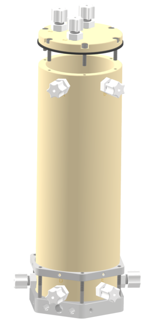
CDI accessories, CO2 Electrolysis Accessories, ...
850.00 €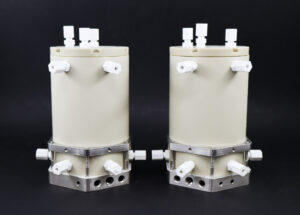
CDI accessories, CO2 Electrolysis Accessories, ...
775.00 €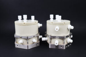
CDI accessories, CO2 Electrolysis Accessories, ...
750.00 €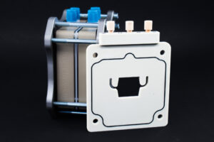
CDI Flow Cells, CO2 Electrolysis Accessories, ...
795.00 € This product has multiple variants. The options may be chosen on the product page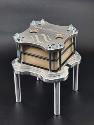
CDI accessories, CO2 Electrolysis Accessories, ...
495.00 €
CO2 Electrolysis Accessories, Electrolysis Accessories, ...
1,250.00 €
CDI accessories, Electrolysis Accessories, ...
595.00 €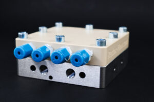
Flow Battery Accessories, Temperature Control for Electrolysis, ...
1,450.00 €
Electrolysis Accessories, Flow Battery Accessories
1,395.00 €
CDI accessories, Electrolysis Accessories, ...
345.00 €
Electrolysis Accessories, Flow Battery Accessories, ...
945.00 €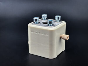
CDI accessories, Electrolysis Accessories, ...
485.00 €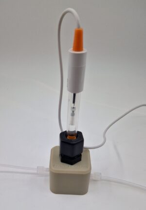
CO2 Electrolysis Accessories, Electrolysis Accessories, ...
395.00 €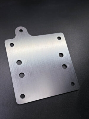
Cell Parts, Flow Battery Accessories
295.00 €