")
Context
The 8 channel battery testers sold by Redox-flow.com have specs where minimum discharge voltages are in the range 1 V to 1.6 V depending on the specific model. For flow batteries it often desired to be able to discharge below 0.5 V and for this reason we are often asked by our costumers if the 8 channel battery testers can discharge below e.g. 1 V. The short answer is yes, but the minimum voltage is not fixed and it depends on many factors, including experimental factors that can be optimised. This white paper is related to explaining this phenomenon.
Introduction
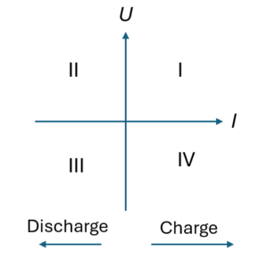
Modern (programmable) power sources and loads are typically referred to how many quadrants in the U-I curve (see xx below). As an example a power source (e.g. for electrolysers) that can only deliver electrical current will only be able to operate in quadrant I, an electronic load will only operate in quadrant II, while high-end and costly electrochemical workstations/potentiostats are able to operate in all four quadrants and can be used for full characterisation of any electrochemical device.
Battery tester (as the 8 channel battery testers sold by Redox-flow.com) are very cost-effective alternatives to costly potentiostats. They can be considered as a combined programmable power source and load can operate in both quadrant I and II. I.e. during charging it is controlled by the power source and during discharge it is controlled by the load. Here it is important to understand that an electronic load is a passive device where the electrical current supplied to the load from the battery is driven by the internal voltage of the battery.
Equivalent Electric Circuit of Battery and Battery Tester
To make quantitative predictions on the minimum discharge voltage it is helpfull to make an equvialent electrical circuit of the battery tester and battery and is shown below, where only discharge is considered.
The battery has an internal resistance (RI) and an internal open circuit voltage (UOCV). On the left side the battery tester measures the ‘external’ cell voltage on the battery (Ucell) through two voltage wires connected to the current collectors on the battery. Ucell is the voltage is reported in the ‘performance’ of the battery. The control of the battery tester can be imagined as being a variable load resistance inside the battery tester (RL). I.e. if RL is low the electrical current (I) in the circuit increases, while if RL is high I will decrease. For simplicity a positive electrical current corresponds in the following to discharge (and not discharge as shown in the four-quadrant picture above)
In addition to the two units, there are also electrical wires for carrying the electrical current between the two units. The wires comes with a resistance (Rw), while the contact points between tester/wire/battery comes with contact resistances (Rc).
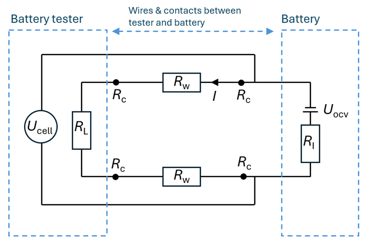
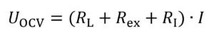
From the equivalent circuit above, it is seen that the total voltage loss (UOCV) across the circuit is given by Ohms law. I.e. the electrical current multiplied with the sum of all the resistances in the circuit. For simplicity all the wire and contact resistances are replaced by Rex= 2Rw+ 4Rc and subscript ex refers to external.
 1a)
1a)
By rearrangement
(1b)
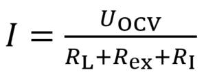
It can be seen that the discharge current can be varied by changing the load resistance inside the battery tester. Also it is seen that the maximum discharge current (Imax) is obtained when RL = 0 Ω and is given by
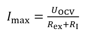
(2)
Again, if the wire/contact resistance are zero (Rex= 0 Ω) the maximum electrical current is only given by the internal resistance of the battery.
The voltage measured on the battery (Ucell) can also be found by circuit analysis and is given by
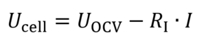
(3)
And is the ‘polarisation curve’ obtained when measuring the voltage-current relation in a battery. The slope of the curve gives the internal resistance of the battery. By inserting eq. 1b into eq. 3, the following relation is obtained
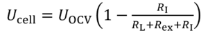
(4)
This equation can be used for analysing the effect of the load and external resistance on the ‘minimum discharge voltage’ (). The maximum discharge current is obtained when = 0 W and
Interested? We’d like to hear from you!
Don’t hesitate to contact us with any kind of inquiries at
sales@redox-flow.com or call Mikkel Kongsfelt at +45-3126-2040

Mikkel Kongsfelt